--- Editing Instructions (Multiple Areas Can Be Selected After Choosing a Function) ---
Step 1. Select an operation from the menu and press the button if necessary.
Step 2. Select the section where you want to apply the function with the mouse to apply the effect.
Please use the editing functions following these steps.
Clicking the line spacing (blank space) in the description will reset the function selection.
For the “Hide” and “Keyworddize” functions, if you do not specify a keyword to replace the text, the text will be hidden; however, the system is designed to add a ▽ to explicitly indicate that section.
Practice
1. Using the GAKKUZAI system, please rewrite the following passage on a page in your notebook.
What does it mean to design an electrical circuit?
Electrical circuits tailored to specific purposes have been extensively studied and published as standard circuit designs. Circuit designers combine these standard circuits to achieve the desired functionality. However, even for the same circuit, the specific electrical energy applied to each part varies depending on the circuit’s purpose.
For example, a circuit to make an LED light up consists solely of an LED connected in series with a resistor that regulates the current to prevent it from becoming too high. The voltage required to make an LED glow varies depending on the type and model of the LED. Furthermore, if the purpose of lighting the LED is to indicate that the power is on, a current of a few milliamps is sufficient; however, for an infrared LED used in an infrared remote control for a TV or similar device, a current of about 1 ampere must be applied momentarily to emit a strong light that reaches a long distance. For this reason, electrical circuit designers must determine the appropriate value for the circuit’s resistance based on the purpose and conditions. This is what electrical circuit design entails.
In practice, few electrical circuits are as simple as one LED and a single resistor; most are complex structures consisting of multiple power sources, numerous resistors, coils, capacitors, and other components. To design an electrical circuit, one must be able to derive equations relating current to impedance, and current, impedance, and voltage—using Kirchhoff’s Current Law (KCL) and Kirchhoff’s Voltage Law (KVL), which will be discussed later—and solve these equations as a system of linear equations.
Kirchhoff's law
Kirchhoff's current law (KCL)
Kirchhoff's current law (KCL) is also known as Kirchhoff's first law. It states that, for any junction A in a circuit network, the sum of the currents flowing into A is equal to the sum of the currents flowing out of A.
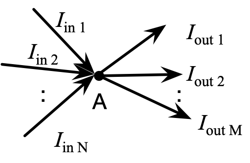
Let the incoming currents be
Iin 1,
Iin 2, ...,
Iin N, and the outgoing currents as
Iout 1,
Iout 2, ...,
Iout M, the following holds true.
Alternatively, if we treat the incoming current as + and the outgoing current as –, the expression becomes as follows.
Kirchhoff's voltage law (KVL)
Kirchhoff's voltage law (KVL) is also known as Kirchhoff's second law. It states that, for any closed loop in a circuit network, the sum of the electromotive forces (EMFs) encountered while traveling around the loop is equal to the sum of the voltage drops. The term “arbitrary closed loop” here means not only that “you may choose any single hole in the mesh,” but also that “you may select any number of cells by following any path along the wires of the mesh, provided that the path forms a closed loop that returns to the starting point.”

Let the electromotive forces along the closed circuit be
V1,
V2, ...,
VN, and let the impedances along the closed circuit be
Z1,
Z2, ...,
ZM, and let the currents flowing through each impedance be
I1,
I2, ...,
IM, then the following expression holds.